Loading - Shipping
When stacking pre-insulated pipes during loading and shipping, the pipes with the largest diameter must be placed below, and the pipes with smaller diameters must be placed on top. The pipes stacked for loading and shipping must be packed according to certain number of ties. If possible, wedges must be placed between the pipe rows in large diameter pipes that will be shipped without being tied. If any, fitting products must be placed on separate pallets or in big bags.
Unloading Pipes from Vehicles
A suitable area must be used for this process when unloading the pipes from the vehicle. The pipes with a diameter up to 114 mm can be unloaded by hand, but for avoiding damaging the insulation, they must not be dragged or dropped on the ground from height. A crane must be used for pipes with a diameter greater than 114 mm. If a vehicle such as a forklift will be used, it must be ensured that the fork in the front does not damage the insulation. In order not to expose the pipe to torsion moment and to ensure work safety, ropes tied at the pipe ends must be used for 12-metre pipes..
Storage of Products in the Field
Pipes must be separated according to their diameters and arranged in a way that decreases (pyramid) at each row. The length of each pile must be 2 metres in maximum.
Fitting products can be stored according to their types or diameters.
If pipes will be stored in areas with a risk of flooding, they must be stacked at a level higher than the ground.
If it is necessary to store for longer than a month, a protective cover must be laid over them. Polyol and isocyanate components transported for joint insulation must be protected from direct sunlight and stored in cool and dry environments.

Excavation and Filling Works
Since pre-insulated pipe systems are generally used in heating and cooling lines, expansion and contraction occur in the pipes. Due to the axial movements that may occur as a result of this expansion and contraction, it is of great importance that the excavation and filling works are carried out in accordance with the directives so that no damage occurs due to the ground where the system is located.
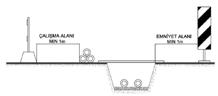
While digging a trench, it must necessarily be secured against landslides. The soil in the trench must be dry and it must be free of stones and other sharp materials that could damage the casing pipe.

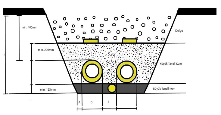
Excavation & Filling Sectional View
As in the excavation image above, the excavation & filling process must be performed in the correct dimensions according to the casing pipe diameters in the table.
|
D Casing Pipe Diameter |
Amin (mm) |
Smin (mm) |
Emin (mm) |
|
90 |
200 |
640 |
200 |
|
110 |
200 |
660 |
200 |
|
125 |
200 |
675 |
200 |
|
140 |
200 |
690 |
200 |
|
160 |
200 |
710 |
200 |
|
180 |
200 |
730 |
200 |
|
200 |
250 |
750 |
250 |
|
225 |
250 |
775 |
250 |
|
250 |
250 |
800 |
250 |
|
280 |
250 |
830 |
250 |
|
315 |
250 |
865 |
250 |
|
355 |
250 |
905 |
250 |
|
400 |
250 |
950 |
250 |
|
450 |
250 |
1000 |
250 |
|
500 |
250 |
1050 |
250 |
|
560 |
300 |
1110 |
300 |
|
630 |
300 |
1180 |
300 |
|
710 |
300 |
1260 |
300 |
|
800 |
300 |
1350 |
300 |
Table: Recommended Duct Section Dimensions
Fine-grained sand filling must be made at a height of at least 200 mm from the upper level of the insulated pipe. Compressing the pipes with fine-grained sand will also increase the friction force, thus helping limit the axial movements to occur in the pipes.
A range of 400 mm - 600 mm is recommended for the minimum filling depth between the upper level of the insulated pipe and the ground. Especially in lines with branch separators, the filling height must not be less than 400 mm in order for the branch pipe can be protected from the loads on the ground. If it is not possible to comply with the minimum filling depth due to the conditions in the field, the top of the filling must be reinforced with concrete or steel sheet.
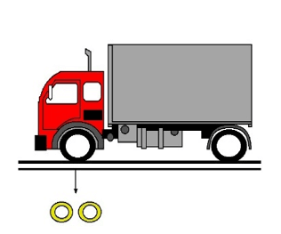
In places with heavy traffic, the extra load that can be created by passing of especially high-tonnage vehicles must be taken into account, and if necessary, the filling depth must be increased. In such cases, the following formula can be made for calculation:

h=0,17× F
h (m) : Filling Depth
F (ton) : Wheel load from a single axis
Field Application
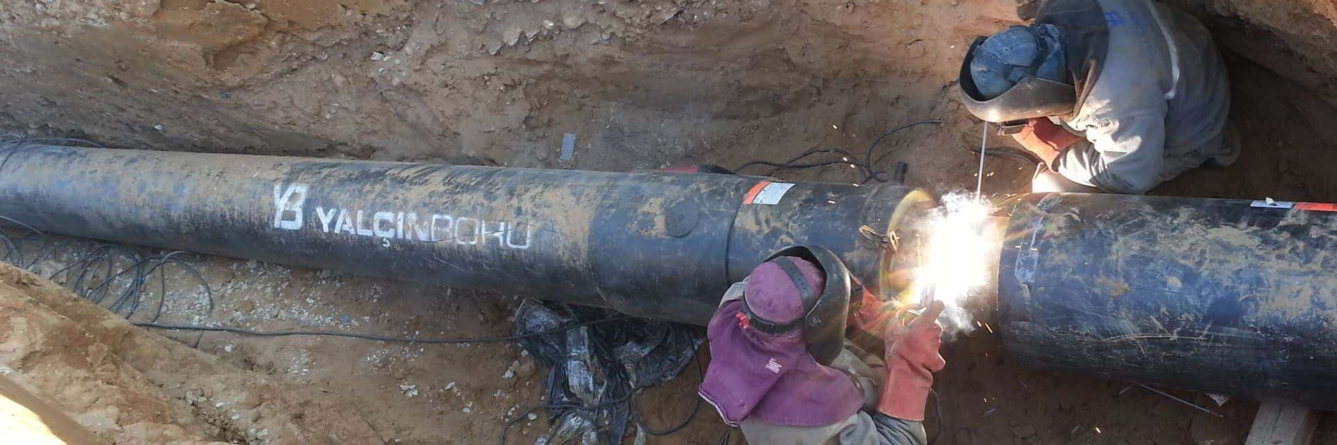
Before the installation and welding of pipes inside or outside the duct, the following points should be checked:
- PE casing pipes or complete heat-shrink joints required for joint insulation must be put on around the pipe.
- If a leak detection system is available, the cables must be checked and kept away from the welding area.
- The non-insulated part at the pipe ends must be 150 mm in minimum, and this part must be cleaned and be free of residues for the welding to be performed properly.
- If preheating is going to be done, PUR, PE casing and signalisation wires must be protected against overheating.
- The exposed pipe end must be capped in order to prevent foreign matters from entering into the line.
After the installation and welding process is completed, the instructions provided by Yalçın Boru and the consumables chart specially prepared for your project must be followed for the correct application of the joint insulation kit.


